How to Read a Circuit Diagram
Circuit diagrams are one of the most crucial components in electrical engineering. They are used to represent the flow of current through a circuit. The graphical representation of a circuit, commonly used in electricity and electronics, does not depict the actual shape and arrangement of individual components but rather an abstract representation of the functions using symbols and the electrical connections between components. This allows for illustrating how a circuit works or identifying issues in an existing circuit. The main purpose of circuit diagrams is to visualize the components and their connections. This is especially important for de-energizing objects to safely work on them without power.
The following section covers the individual elements of a complete circuit diagram, explains what a circuit diagram is, and provides guidance on how to read them. Additionally, various overviews briefly explain what each circuit symbol means.
What is a Circuit Diagram?
Electrical circuit diagrams are used wherever a detailed overview of individual elements and their electrical connections is necessary. In addition to providing general information, circuit diagrams primarily serve the following purposes:
- As a Preliminary Step for PCB Layout Design: In CAD software, components and their connections on a printed circuit board (PCB) are drawn in a circuit diagram. This diagram is then used to create a netlist for the layout.
- As a Preliminary Step for Designing Simple Circuits: For basic circuits. More complex electrical circuits would become too large and cumbersome if represented graphically.
- As Input for Circuit Simulation: Allows for the verification of certain functions before actual implementation and for optimizing or adjusting component parameters to meet specific requirements.
In practice, terms such as circuit diagram, wiring diagram, or schematic sketch are often used interchangeably. To create circuit diagrams, standard circuit symbols are used, which can be found in standards such as IEC 60617. Lines between the symbols represent conductive connections. When additional components are added to the electrical system, it is useful to label them with a reference designation according to IEC 81346. This simplifies communication between the electronic and mechanical departments within a company.
What Does a Circuit Diagram Consist Of?
Circuit diagrams, wiring diagrams, or schematic sketches provide a detailed representation of how motors, cables, relays, switches, wires, and devices need to be connected in practice to form a closed and functional circuit. Every diagram consists of the same components, which simplifies handling and learning for beginners in electronics.
How to Read a Circuit Diagram
Reading an electronic circuit or a circuit diagram can quickly become overwhelming for novices. To read a circuit diagram correctly, some basic knowledge and experience are essential. In electronics, it is crucial to master and understand certain fundamentals to avoid errors and hazards. Therefore, it is necessary to familiarize oneself with the relevant basics, electronic components, various circuit techniques, as well as control systems and technology beforehand.
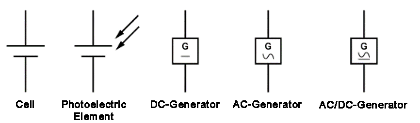
Recognizing Power Sources or Power Supplies
Every circuit typically has a power supply. In the circuit diagram, the power source is identified by a long bar for positive and a short bar for negative.
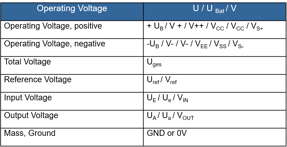
In many circuits, the diagram only shows the operating voltage level. The information about the required voltage (operating, input, and output voltage) is usually indicated by a U or V. The sign indicates the type of voltage. A plus (+) sign indicates a positive operating voltage, while a minus (-) sign indicates a negative voltage.
Below are listed various types and their designations:
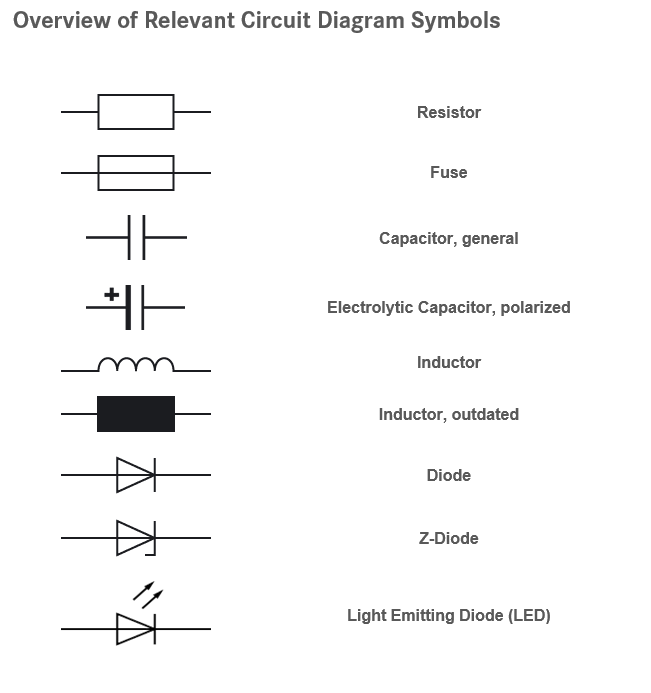
Circuit diagram symbols
The various electrical components can be identified in the circuit diagram by their respective symbols. Unfortunately, due to various standards that have become established around the world, the representation of components is not always consistent. The following overview shows examples of the most important parts that can occur in any circuit and their corresponding symbols:
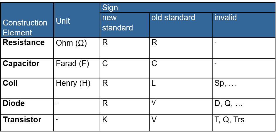
In addition to the individual symbols, electrical components can also be classified and distinguished by their markings. Since individual components usually appear several times in a circuit, a corresponding number or index is added to the respective letters. This makes it easier to define a specific component when it is mentioned in a parts list or instruction manual. The following table shows various symbols according to the old and new standards, but also includes invalid symbols that are often used in unprofessional circuits.